Wiring Diagrams
Below are the wiring diagrams for U.S. models depending on the year of your car. (I hope I have all variations.)
Note that the black boxes are interchangeable left/right.
You must explicitly check your wiring as described below if any of the following conditions exist:
- You have other than a U.S. model. (E-mail me if you verify your non U. S. model and I'll try to update the procedure.)
- Your wiring connections do not match the colors specified for your model year.
- Your headlight actuator wiring has been previously modified.
If any of the above conditions exist, you need to check your wiring using a multi-meter or a simple 12V tester.
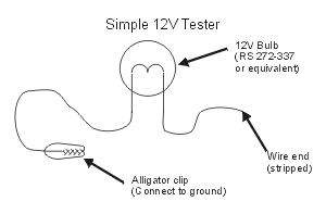
Warnings:
- The headlight actuator motors can move the headlights rapidly and unexpectedly when energized! Always de-energize the system before working near the headlights, or connecting or disconnecting any connectors.
- These wiring checks require working on energized connectors. Do not let exposed metal connectors come in touch with metal body, frame or engine parts.
- Observe all standard warnings.
To check the correct wiring (only one side needs to be checked if both sides have identically colored wires):
Raise the headlights with the dash switch and de-energize the circuit.
After verifying the actuators are de-energized, disconnect the actuator from the wiring harness by pressing the plastic tab on the upper half of the connector and pulling the lower half downward. Unhook the upper half by reaching behind it, pressing the two soft clips holding the connector to the frame, and pull it free. (On later years, only the lower part of the connector is attached to the frame.)
Move the upper half (female) connector away from the actuator and install the Retractor and Head fuses. This connector will now be energized.
Verify the following voltages exist at the upper half (female) of the connector with the dash switch in the specified position:
| colspan=2Color of wire | colspan=2Dash switch | ||
|---|---|---|---|
| 1989-1993 | 1994-1997 | UP | DOWN |
| Brown | Brown | align=right+12V | align=right+12V— |
| Black | Black | align=right0V | align=right0V— |
| Red/Yellow | Red/Yellow | align=right+12V | align=right0V— |
| White/Red | Red/Green | align=right0V | align=right+12V— |
| Green/Blue | Green/Blue | align=right0V | align=right0V— |
Remove the fuses and place the dash switch back in the UP position.
Re-attach the two connectors, and push the attaching clip back into the frame. Warning: Re-attaching the connector with the fuses installed can cause serious injury.
Verify the dash switch is UP, and re-install the fuses.
Test the circuit by cycling the headlights up and down with the dash switch, and by turning the headlights on and off.
If all voltages and wire colors are as expected, the installation of the wink can be completed.
Next Index